


Before figuring out these questions, we first need to understand the following terms:
- Pigtail: used in the terminal box to connect the optical fiber in the optical cable, and connect the pigtail and jumper through the terminal box coupler (adapter).
- Jumper: Both ends of the jumper are active connectors, which serve to connect the pigtail and the equipment.
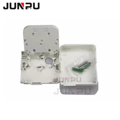
- Optical cable terminal box: a box that protects the optical cable and pigtail at the terminal of the optical cable laying.
- Fiber optic coupler: a movable connection for two optical fibers or pigtails, commonly known as a flange.
- Fiber optic terminal box: a terminal connector of an optical cable, one end of which is an optical cable and the other end is a pigtail, which is equivalent to a device that splits an optical cable into a single optical fiber.
- Fiber fusion box: It is used to connect two optical cables into one long optical cable. Fiber terminal box and fiber fusion box cannot be used interchangeably. The optical cable and the optical terminal are connected through the fiber terminal box, that is, only the pigtail can be inserted into the optical terminal.
- Coupler: It can only connect two pigtails and has interfaces such as SC/PC FC/PC, while the optical cable and the pigtail are fused by a fusion splicer and are dead.
- Terminal box VS fusion box: The former is the fusion of the optical cable and the pigtail, and the latter is the fusion between the optical cables.
- Splice box VS terminal box: The splice box is fully sealed and waterproof, but it cannot fix the pigtail; the terminal box is not waterproof, and the internal structure can fix the optical cable on one side and the pigtail on the other side.
- Pigtail VS jumper: Only one end of the pigtail is a movable joint; both ends of the jumper are movable joints, there are many types of interfaces, different interfaces require different couplers, and the jumper can be divided into two and used as a pigtail.
Connection relationship between optical cable, terminal box and pigtail
1: The outdoor optical cable is connected to the terminal box, the purpose is to fuse the optical fiber in the optical cable with the pigtail, and lead it out through the jumper.
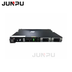
2: Connect the optical fiber jumper to the optical fiber transceiver, the purpose is to convert the optical signal into an electrical signal.
3: The optical fiber transceiver leads out the electrical signal, and the transmission medium used is the twisted pair. At this time, the twisted pair can be connected to the RJ-45 port of the network device. So far, the conversion of optical and electrical signals has been completed.
Note: Many network devices now have optical ports (optical fiber interfaces), but if there is no optical distribution module (similar to the function of optical fiber transceiver), this port cannot be used.
The role of optical cable, terminal box, and pigtail
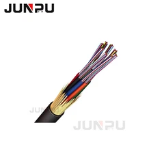
The role of the optical cable terminal box: terminate the optical cable, connect the fiber core and pigtail in the optical cable, the internal structure of the optical cable terminal box, the connected optical cable can have multiple cores,
For example: a 4-core optical cable (there are 4 fiber cores in the optical cable), then, this optical cable can be fused to produce up to 4 pigtails after passing through the terminal box, that is, 4 jumpers are led out. If only 2 are fused, 2 jumpers are also led out.
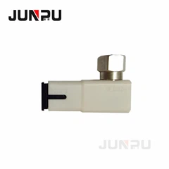
Pigtail: There is a connector at one end, and the other end is the broken end of an optical cable core. Through fusion, it is connected to other optical cable cores.
The role of the pigtail: It is mainly used to connect the connectors at both ends of the optical fiber. One end of the pigtail is fused with the optical fiber connector, and the other end is connected to the optical fiber transceiver or optical fiber module through a special connector to form an optical data transmission path. Generally, we cannot buy pure pigtails, but jumpers as shown in the figure. Once the middle is cut, it becomes a pigtail.
ST, SC, and FC fiber optic connectors are standards developed by different companies in the early days. They have the same effect and each has its own advantages and disadvantages. The following is a detailed introduction.
- ST and SC connectors are commonly used in general networks.
- After the ST head is inserted, it rotates half a circle and has a bayonet to fix it. The disadvantage is that it is easy to break;
- The C connector is directly plugged in and out, which is very convenient to use, but the disadvantage is that it is easy to fall out;
- The FC connector is generally used in telecommunications networks. There is a nut screwed onto the adapter. The advantages are firm and dust-proof, and the disadvantage is that the installation time is slightly longer.
- The MTRJ type fiber optic jumper consists of two high-precision plastic molded connectors and optical cables. The outer parts of the connector are precision plastic parts, including a push-pull plug-in clamping mechanism. It is suitable for indoor applications in telecommunications and data network systems.
Types of fiber optic interface connectors
TF-FC, TF-ST, TF-FC/APC, TF-SC/APC, TF-SC
Fiber optic connectors, that is, fiber optic connectors that connect to optical modules, also have many types, and they are not interchangeable. People who don't often come into contact with optical fibers may mistakenly think that the optical fiber connectors of GBIC and SFP modules are the same, but they are not. SFP modules are connected to LC optical fiber connectors, while GBIC is connected to SC optical fiber connectors. The following is a detailed description of several commonly used optical fiber connectors in network engineering:
① FC type optical fiber connector: The external reinforcement method is a metal sleeve, and the fastening method is a screw buckle. Generally used on the ODF side (most used on the patch panel)
② SC type optical fiber connector: The connector that connects the GBIC optical module has a rectangular shell and a plug-in latch type fastening method without rotation. (Most used on router switches)
③ ST type optical fiber connector: Commonly used in optical fiber patch panels, the shell is round, and the fastening method is a screw buckle. (For 10Base-F connections, the connector is usually ST type. Commonly used in optical fiber patch panels)
④ LC type optical fiber connector: The connector that connects the SFP module is made of a modular jack (RJ) latch mechanism that is easy to operate. (Commonly used in routers)
⑤ MT-RJ: Square fiber optic connector with integrated transceiver, one end with dual-fiber transceiver
Introduction to various types of fiber optic interfaces
1. Fiber optic connector
- FC round with thread (mostly used on patch panels)
- ST snap-on round;
- SC snap-on square (mostly used on routers and switches)
- PC micro-spherical grinding and polishing;
- APC is 8 degrees and micro-spherical grinding and polishing
- MT-RJ square, one end with dual-fiber transceiver (useful on Huawei 8850)
Fiber optic module: generally supports hot-swap,
- GBIC Giga Bitrate Interface Converter, the fiber optic interface used is mostly SC or ST type
- SFP small package GBIC, the fiber used is LC type
Fiber optic used:
- Single mode: L, wavelength 1310 single mode long distance LH wavelength 1310,1550
- Multimode: SM Wavelength 850
SX/LH means single-mode or multi-mode optical fiber can be used
In the marking of pigtail connectors, we often see "FC/PC", "SC/PC", etc., and their meanings are as follows:
- The part before "/" indicates the connector model of the pigtail.
- The "SC" connector is a standard square connector, which is made of engineering plastic and has the advantages of high temperature resistance and not easy to oxidize. The side optical interface of the transmission equipment generally uses the SC connector.
- The "LC" connector is similar in shape to the SC connector, but smaller than the SC connector.
- The "FC" connector is a metal connector, which is generally used on the ODF side. The number of pluggable times of metal connectors is more than that of plastic.
There are many types of connectors. In addition to the three types introduced above, there are also MTRJ, ST, MU, etc.
- The part after "/" indicates the cross-section process of the optical fiber connector, that is, the grinding method.
- "PC" is most widely used in the equipment of telecom operators, and its connector cross-section is flat.
- The attenuation of "UPC" is smaller than that of "PC" and is generally used for equipment with special requirements. Some foreign manufacturers use FC/UPC for internal fiber jumpers in ODF racks, mainly to improve the indicators of the ODF equipment itself.
2. Fiber Optic Connector
Fiber optic connector is a device for detachable (movable) connection between optical fibers. It precisely connects the two end faces of optical fibers so that the light energy output by the transmitting optical fiber can be coupled to the receiving optical fiber to the maximum extent and the impact on the system caused by its involvement in the optical link can be minimized. This is the basic requirement of fiber optic connectors. To a certain extent, fiber optic connectors also affect the reliability and performance of optical transmission systems.
Fiber optic connectors can be divided into single-mode and multi-mode connectors of common silicon-based optical fibers according to the transmission medium, and other fiber optic connectors such as plastic as the transmission medium; according to the structure of the connector, they can be divided into various forms such as FC, SC, ST, LC, D4, DIN, MU, MT, etc. The following are some of the more common fiber optic connectors currently:
(1) FC fiber optic connector
This type of connector was first developed by NTT of Japan. FC is the abbreviation of Ferrule Connector, indicating that its external reinforcement method is a metal sleeve and the fastening method is a screw buckle. At first, the FC type connector used a ceramic pin docking port. This type of connector has a simple structure, is easy to operate and manufacture, but the fiber end face is sensitive to dust and is prone to Fresnel reflection, making it difficult to improve the return loss performance. Later, this type of connector was improved by using a spherical pin (PC) with a butt end face, while the external structure remained unchanged, which greatly improved the insertion loss and return loss performance.
(2) SC type fiber optic connector
This is a fiber optic connector developed by NTT Corporation of Japan. Its shell is rectangular, and the structural dimensions of the pin and coupling sleeve used are exactly the same as those of the FC type. The end face of the pin is mostly ground by PC or APC type; the fastening method is a plug-in latch type, which does not require rotation. This type of connector is low-priced, easy to plug and unplug, has small insertion loss fluctuations, high compressive strength, and high installation density.
ST and SC interfaces are two types of fiber optic connectors. For 10Base-F connections, the connector is usually of ST type, and for 100Base-FX, the connector is mostly of SC type. The core of the ST connector is exposed, and the core of the SC connector is inside the connector.
(3) Biconic Connector
The most representative product of this type of fiber optic connector was developed by Bell Laboratories in the United States. It consists of two precision molded cylindrical plugs with truncated cones at the end and a coupling component with a biconical plastic sleeve inside.
(4) DIN47256 fiber optic connector
This is a connector developed by Germany. The structural dimensions of the pin and coupling sleeve used in this connector are the same as those of the FC type, and the end face is processed by PC grinding. Compared with the FC type connector, its structure is more complicated. There is a spring in the internal metal structure to control the pressure, which can avoid damage to the end face due to excessive plugging pressure. In addition, the mechanical precision of this connector is higher, so the insertion loss value is smaller.
(5) MT-RJ connector
MT-RJ originated from the MT connector developed by NTT. It has the same latching mechanism as the RJ-45 LAN electrical connector. The optical fiber is aligned by the guide pins installed on both sides of the small sleeve. To facilitate connection with the optical transceiver, the optical fiber on the connector end face is designed with a dual-core (0.75mm spacing). It is the next generation of high-density optical fiber connector mainly used for data transmission.
(6) LC connector
The LC connector was developed by the famous Bell Research Institute and is made of an easy-to-operate modular jack (RJ) latching mechanism. The size of the pin and sleeve used is half of the size used by ordinary SC, FC, etc., which is 1.25mm. This can increase the density of optical fiber connectors in the optical fiber distribution frame. At present, in the single-mode SFF field, LC type connectors have actually occupied a dominant position, and their application in multi-mode is also growing rapidly.
(7) MU connector
The MU (Miniature unit Coupling) connector is the world's smallest single-core fiber connector developed by NTT based on the currently most commonly used SC connector. This connector uses a 1.25mm diameter sleeve and a self-retaining mechanism. Its advantage is that it can achieve high-density installation. Using the MU's 1.25mm diameter sleeve, NTT has developed a series of MU connectors. They include socket connectors for optical cable connections (MU-A series); backplane connectors with self-retaining mechanisms (MU-B series); and simplified sockets for connecting LD/PD modules and plugs (MU-SR series). With the rapid development of optical fiber networks towards larger bandwidths and larger capacities and the widespread application of DWDM technology, the demand for MU connectors will also grow rapidly.