


The fusion loss at the fiber joint is related to the fiber itself and the fiber fusion. Efforts to reduce the fusion loss at the fiber joint can increase the transmission distance of the fiber relay amplification and improve the attenuation margin of the fiber link.
Main factors affecting fiber fusion loss
There are many factors that affect fiber fusion loss, which can be roughly divided into two categories: fiber intrinsic factors and non-intrinsic factors.
Intrinsic factors:
Fiber intrinsic factors refer to the fiber itself, which mainly include four points: ① Inconsistent fiber mode field diameter; ② Mismatch between the core diameters of the two fibers; ③ Non-circular cross section of the fiber core; ④ Poor concentricity between the core and the cladding. Among them, the inconsistent fiber mode field diameter affects Zda. According to the recommendations of CCITT (International Telegraph and Telephone Consultative Committee), the tolerance standards for single-mode optical fibers are as follows: mode field diameter: (9~10μm)±10%, that is, the tolerance is about ±1μm; cladding diameter: 125±3μm; mode field concentricity error ≤6%, cladding non-circularity ≤2%.
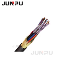
Fiber fusion splicing technology.jpg
Non-intrinsic factors:
Non-intrinsic factors that affect fiber splicing loss are splicing technology.
①Axis misalignment: The core of single-mode optical fiber is very thin, and the axis misalignment of two butt-jointed optical fibers will affect the splicing loss. When the misalignment is 1.2μm, the splicing loss reaches 0.5dB.
②Axis tilt: When the fiber cross section is tilted by 1°, about 0.6dB of splicing loss is generated. If the splicing loss is required to be ≤0.1dB, the inclination angle of the single-mode optical fiber should be ≤0.3°.
③End face separation: If the connection of the active connector is not good, it is easy to cause end face separation, resulting in large connection loss. When the discharge voltage of the optical fiber fusion splicer is low, end face separation is also easy to occur. This situation can generally be found in optical fiber fusion splicers with tensile testing functions.
④End face quality: When the flatness of the optical fiber end face is poor, loss and even bubbles will also occur.
⑤ Physical deformation of optical fiber near the splicing point: The tensile deformation of the optical cable during the installation process, the excessive pressure of the clamped optical cable in the splicing box, etc., will affect the splicing loss, and even several splicings cannot improve it.
Other factors:
The operation level of the splicing personnel, the operation steps, the fiber coiling process level, the electrode cleanliness of the optical fiber splicing machine, the splicing parameter settings, the cleanliness of the working environment, etc. will all affect the value of the splicing loss.
Measures to reduce the splicing loss of optical fiber
Use the same batch of high-quality bare fiber on a line:
For the same batch of optical fibers, their mode field diameters are basically the same. After the optical fiber is disconnected at a certain point, the mode field diameters between the two ends can be regarded as consistent. Therefore, splicing at this disconnection point can reduce the influence of the mode field diameter on the optical fiber splicing loss to the Zdi level. Therefore, it is required that the optical cable manufacturer use the same batch of bare fibers, produce continuously according to the required cable length, number them sequentially on each coil and distinguish the A and B ends, and do not skip numbers. When laying optical cables, they must be laid in the order of the determined routes according to the numbers, and the B end of the front cable must be connected to the A end of the next cable, so as to ensure that the cable can be welded at the disconnection point when connected, and the welding loss value is minimized.
Erection of optical cables shall be carried out as required:
During the installation of optical cables, it is strictly forbidden to make small circles, folds and twists of optical cables. More than 80 people must be employed to construct 3km of optical cables, and more than 100 people must be employed to construct 4km of optical cables, and 6 to 8 intercoms must be equipped; in addition, the cable laying method of "walking in front and following behind, and putting the optical cable on the shoulder" can effectively prevent the occurrence of back buckles. The traction force shall not exceed 80% of the allowable value of the optical cable, and the instantaneous traction force shall not exceed 1**%. The traction force shall be added to the reinforcement of the optical cable. The laying of optical cables shall be strictly in accordance with the requirements of optical cable construction, so as to minimize the probability of optical fiber damage during optical cable construction and avoid the increase of welding loss caused by damage to the optical fiber core.
Select experienced fiber splicers for splicing:
Nowadays, most of the splicing is done automatically by fiber splicing machines, but the level of the splicer directly affects the size of the splicing loss. The splicer should strictly follow the fiber splicing process flow chart for splicing, and the splicing loss of the splicing point should be tested with OTDR during the splicing process. Those that do not meet the requirements should be re-splice. For points with large splicing loss values, the number of repeated splicing should be 3 to 4 times. When the splicing loss of multiple optical fibers is large, a section of the optical cable can be cut off and re-splice.
The splicing of optical cables should be carried out in a clean environment:
It is strictly forbidden to operate in the open air in dusty and humid environments. The optical cable splicing parts, tools and materials should be kept clean, and the optical fiber joints should not be allowed to get damp. The optical fiber to be cut must be clean and free of dirt. The optical fiber must not be exposed to the air for too long after cutting, especially in dusty and humid environments.
Choose a high-precision fiber end cutter to prepare the fiber end face:
The quality of the fiber end face directly affects the size of the fusion loss. The cut fiber should be a flat mirror surface without burrs and defects. The axis inclination of the fiber end face should be less than 1 degree. The high-precision fiber end face cutter not only improves the success rate of fiber cutting, but also improves the quality of the fiber end face. This is especially important for the fusion points that OTDR test cannot reach (i.e. OTDR test blind spots) and fiber maintenance and repair.
Correct use of fiber fusion splicer:
The function of the fiber fusion splicer is to fuse two optical fibers together, so the correct use of the fiber fusion splicer is also an important measure to reduce the fiber splicing loss. According to the type of optical fiber, correctly and reasonably set the fusion parameters, pre-discharge current, time and main discharge current, main discharge time, etc., and remove the dust in the fiber fusion splicer in time during and after use, especially the dust and fiber fragments in the fixture, mirrors and V-grooves.
Before each use, the fiber fusion splicer should be placed in the fusion environment for at least fifteen minutes, especially in places where the environment is very different from that of use (such as indoors and outdoors in winter). According to the current air pressure, temperature, humidity and other environmental conditions, reset the discharge voltage and discharge position of the fiber fusion splicer, and reset the V-groove driver and make other adjustments.
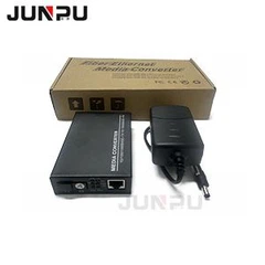
Measures to reduce fiber fusion loss.jpg
Measurement of fiber splice loss
Optical loss is an important indicator of the quality of a fiber joint. There are several measurement methods to determine the optical loss of a fiber joint, such as using an optical time domain reflectometer (OTDR) or a fusion joint loss evaluation scheme.
1. Fusion joint loss evaluation
Some fiber fusion splicers use a cross-sectional arrangement system for fiber imaging and measuring geometric parameters. By observing the fiber from two perpendicular directions, the computer processes and analyzes the image to determine the cladding offset, core distortion, fiber outer diameter change and other key parameters, and uses these parameters to evaluate the joint loss. The splice loss obtained by the joint and its loss evaluation algorithm may be quite different from the actual splice loss.
2. Use an optical time domain reflectometer (OTDR)
An optical time domain reflectometer is also called a backscattering instrument. Its principle is: when a light pulse is transmitted into an optical fiber, a trace amount of light scattered in the optical fiber returns to the light source side, and the time base can be used to observe the degree of reflected return light. Since the mode field diameter of the optical fiber affects its backscattering, the optical fibers on both sides of the joint may produce different backscattering, thereby obscuring the true loss of the joint. If the loss of the joint is measured from two directions and the average of the two results is calculated, the human error of the one-way OTDR measurement can be eliminated. However, in most cases, the operator only measures the joint loss from one direction, and the result is not very accurate. In fact, the loss caused by the optical fiber with a mismatched mode field diameter may be 10 times greater than the intrinsic joint loss itself.