


Transmission medium
Single-mode optical fiber is generally yellow, with blue connectors and longer transmission distances. Multimode fiber is generally orange or gray, with cream or black connectors and shorter transmission distances.
Connector structure
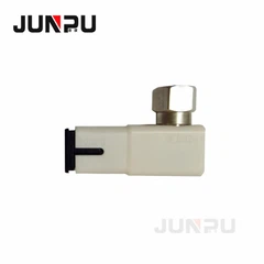
Connector design standards include FC, SC, ST, LC, MTRJ, MPO, MU, SMA, FDDI, E2000, DIN4 and D4. Cables are classified by the connectors on each end of the cable; some of the most common cable configurations include FC–FC, FC–SC, FC–LC, FC–ST, SC–SC, and SC–ST. [clarification needed]
Insert core cap
The connector plugs into a core cover that conforms to APC, UPC, or PC configurations. [2] The UPC ferrule cover is flat and used by the State Administration of Radio, Film and Television and early CATV. The insert core cover of the APC connector is angled (approximately 30°, ±5°). [3] To reduce reflections from the back of the connector, UPC polish is used. The industry standard is a maximum value of −40 dB for PC backreflection measurements and −50 dB for UPC backreflection measurements. If less back-reflection is required, an APC may be required. APC connectors have an 8° angled cutout on the ferrule. These connectors can be identified by their green color. APC polished connectors have a standard reflectivity maximum of −60 dB. APC fiber ends have low back-reflection even when disconnected. [4]
Armored fiber optic patch cord
Armored fiber optic patch cords are armored with a flexible protective tube (usually stainless steel) inside the outer sheath to protect the glass fibers inside. It will not be damaged even if stepped on, and it has anti-rodent function. [5]
Bend-insensitive fiber optic patch cords
Bend-insensitive fiber optic patch cords are widely used in fiber-to-the-home (FTTH). Single-mode bend-insensitive fibers include G657A1, G657A2, G657B2, and G657B3. [6]
Mode adjustment jumper
Mode adjustment jumpers are required if Gigabit 1000 Base-LX routers and switches are installed into existing multimode cabling installations [7]. The transceiver module transmits only single-mode 1300 nm signals, but existing networks are built using multimode cables.
When a single-mode laser is aimed at the center of a multimode fiber, the signals along the various paths in the fiber to the far end spread out in time, making the rapid transitions between light and dark indistinguishable, and the problem increases as the fiber length increases. Increase. This time spreading is called differential mode delay (DMD), and it limits the fiber length over which Gigabit Ethernet signals can be transmitted. Mode conditioning patch cords eliminate these multiple signals by aiming the single-mode emission away from the center of the multimode fiber core. This offset emission produces an emission signal similar to typical multimode light-emitting diode (LED) emission.

